Overview
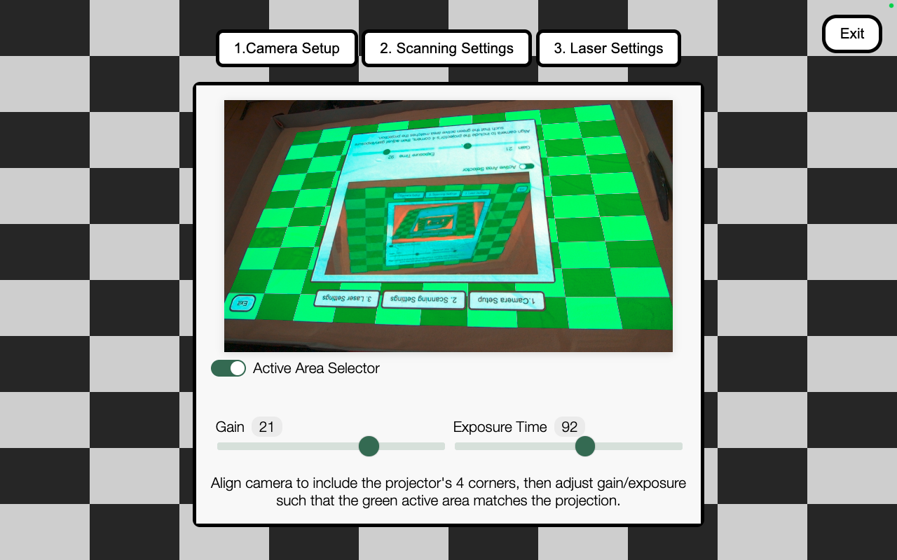
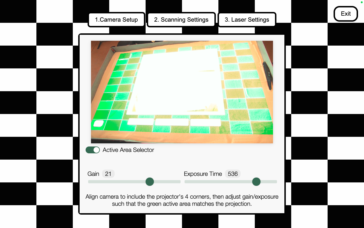
The AnySurface Camera Calibrator is the user interface for Simtable’s AnySurface technology. AnySurface generates a correspondence map between a camera and a projector, enabling browser events initiated by a laser pointer. This tool was built for the Simtable—a digital, interactive sandtable with a browser-based UI that can be controlled using a laser pointer.
The calibrator consists of three primary screens that guide users through configuring camera settings required to generate an accurate correspondence map and enable reliable laser tracking. While the underlying techniques are relatively simple machine vision, the impact is significant: the results of this work allow a new generation of Simtable to ship with a standard webcam instead of an expensive machine-vision camera. This dramatically reduces hardware costs, simplifies setup, and opens new markets for the company to explore in 2026.
This project required deep work with the Media Capture API, including creating video streams and dynamically adjusting camera constraints. Because the goal was to support any webcam, I had to account for inconsistent terminology and behavior across camera manufacturers and the UVC Video Controller specification. I also studied camera intrinsics and extrinsics to better understand how cameras model the world and how their physical placement affects calibration.
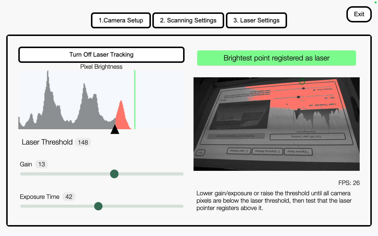
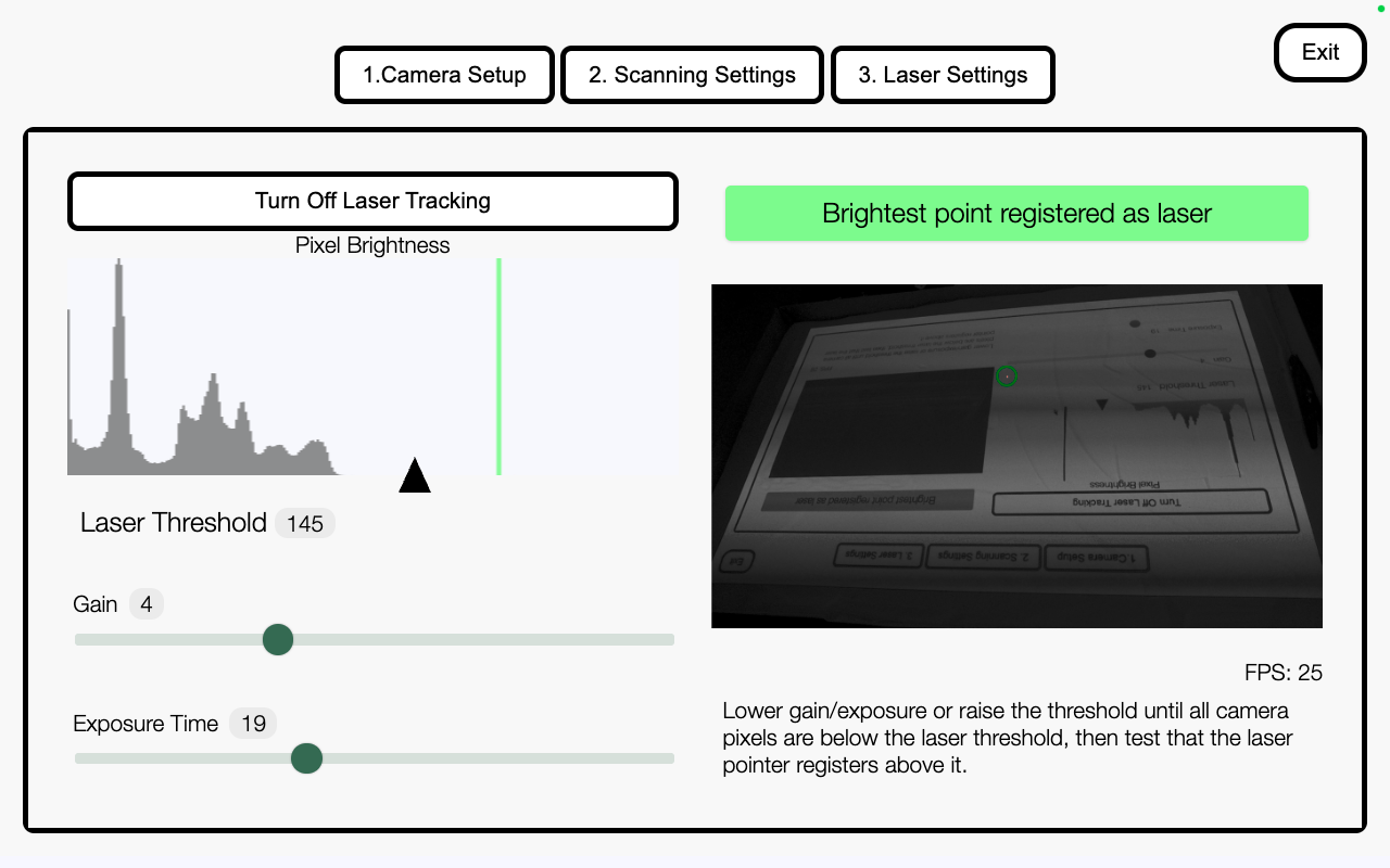
I additionally worked extensively with the Canvas API to build real-time interfaces that provide immediate visual feedback on live camera streams. This included manipulating raw image data from the live video stream to highlight pixels exceeding brightness thresholds, critical for laser detection. To keep performance responsive, I throttled requestAnimationFrame() calls in alignment with the browser’s render cycle, limiting CPU overhead. I also built a dynamic histogram that computes pixel brightness in real time and uses linear interpolation to smooth animations between frames—giving users fast, intuitive feedback while processing live camera data in the browse
Technologies / Tools
- Javascript Custom Web Component integrated in AngularJS
- MediaStream API and WebRTC
- Dynamic rendering with requestAnimationFrame() and Canvas API
My role
I have been a solo developer on the camera calibrator component. I am responsible for the work outlined in the Overview sections. In addition to that information, there are a few architectural pieces I am proud of to note:
- This component can be integrated into any web application, regardless of framework, because it is implemented as a plain JavaScript custom web component. It has no external dependencies and requires no build step. To initialize the component, the consuming application passes a camera configuration object as an attribute, which the web component can read from and update directly.
- Incorporating this component into our main product, AnyHazard, resulted in laser tracking that is roughly 10× faster. Previously, the system relied on a Python-based laser server and a dedicated machine vision camera. With this component, all laser tracking now runs in a browser worker thread, eliminating server overhead and moving real-time vision processing directly into the client environment.